
Building a Tiny Operating System from Scratch
Sameera Madushan / May 16, 2026
A long time ago, I read Operating System Concepts by Abraham Silberschatz, Greg Gagne, and Peter Baer Galvin, and it sparked a deep curiosity in me about how operating systems actually work under the hood. Since then, I’ve wanted to build a small operating system from scratch to truly understand what happens at the lowest level of a computer system.
That curiosity eventually turned into this project, where I started building a small OS phase by phase, exploring everything from the boot process to memory management and process scheduling along the way. This article documents that journey as a timeline, capturing each phase of development, what I built, and what I learned while slowly working toward a working operating system.
Development Timeline
This project is being built step by step in small phases, with each phase focusing on one core concept of operating system development. The goal is not speed, but understanding what each layer of a system actually does.
-
Phase 1 - Bootloader + Screen Output
- The first step is getting the system to actually boot. Writing a custom bootloader and printing directly to the screen using VGA memory, without any operating system support.
-
Phase 2 - Protected Mode + GDT
- Switching the CPU from 16-bit real mode into 32-bit protected mode, setting up the Global Descriptor Table (GDT), and defining memory segments properly.
-
Phase 3 - Interrupts + Keyboard
- Handling hardware interrupts, building basic keyboard input support, and allowing the system to respond to user input.
-
Phase 4 - Memory Manager
- Implementing a basic memory management system, understanding paging, and handling memory allocation in a kernel environment.
-
Phase 5 - Processes + Scheduler
- Introducing multitasking, creating simple processes, and building a basic scheduler to switch between processes.
-
Phase 6 - Shell + Polish
- Building a simple command-line shell on top of the kernel and polishing the system into a usable minimal OS environment.
Phase 1 : Bootloader + Screen Output
Before we even write a single line of Assembly or C code, it’s important to understand what actually happens when a computer powers on, because everything we build later depends on this exact sequence.
When you press the power button, the CPU begins execution from a fixed, hardware-defined address called the reset vector. On x86-64 machines, this address is always 0xFFFFFFF0, hardwired into the CPU itself. This address points to the firmware, which is stored in a non-volatile flash ROM chip soldered onto the motherboard, meaning it retains its contents even when the power is off. This is where execution actually begins.
The firmware then runs a series of checks called POST (Power-On Self Test), verifying that essential hardware like RAM, CPU, and connected devices are working correctly. Once POST passes, the firmware begins searching through storage devices such as USB drives and hard disks, looking for something bootable. It reads the first 512 bytes of each device and checks if the last two bytes are 0x55 and 0xAA. This two-byte sequence is called the boot signature. Only if that signature is present does the firmware copy those 512 bytes into RAM at memory address 0x7C00 and jump to it, handing control over to whatever code is sitting there. That 512-byte region on disk is called the Master Boot Record (MBR), and the code living inside it is our bootloader.
At this point, the CPU is running in real mode, a 16-bit execution environment that every x86-64 machine starts in for backward compatibility. In real mode there is no memory protection, no virtual memory, and a hard limit of 1 MB of addressable memory. The only help we have available is a set of firmware routines called BIOS interrupts, which allow us to do basic operations like printing to the screen and reading from disk without writing drivers ourselves. This is the environment our bootloader runs in, and everything we want to do at this stage must fit within those first 512 bytes.
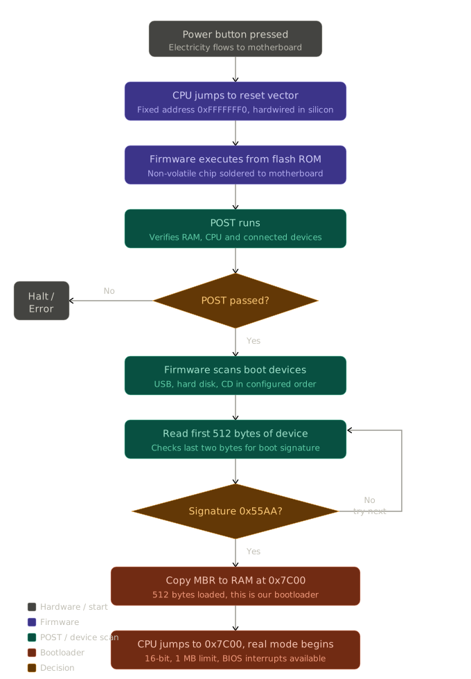
Now let us go through our bootloader code step by step and understand exactly what each part is doing.
The full source code for this phase is available in the repository. You can view the exact commit here: Phase 1 Bootloader Commit
Also Read: Assembly 101: How Programs Speak to the Machine
Setting up the environment
The first thing we do is tell the assembler two important things. [BITS 16] tells it we are writing 16-bit code, meaning the default operand and address size for every instruction will be 16 bits.
This matters because the CPU powers on in real mode, which is a 16-bit execution environment. In real mode, the default integer operand size is 16 bits, so instructions like mov ax, 5 move a 16-bit value. The registers available to us directly are the 16-bit ones: ax, bx, cx, dx, si, di, sp, and bp. We cannot use 32-bit registers like eax or ebx without special override prefixes, and we cannot address more than 1 MB of memory.
It is worth noting that [BITS 16] does not change the CPU behavior at all. It only tells NASM how to encode the instructions we write. If we wrote [BITS 32] but ran the code in real mode, the CPU would misinterpret every instruction because the byte sequences would mean something entirely different in that context.
[ORG 0x7C00] tells the assembler that our code will be loaded at address 0x7C00 in memory, so all labels and addresses must be calculated relative to that. To understand why our code lands at 0x7C00, we need to understand how real mode addresses memory.
In real mode, no single register can hold a full 20-bit address because all general-purpose registers are 16 bits wide. To access the full 1 MB memory space, the CPU combines a 16-bit segment and a 16-bit offset.
- A segment (starting location)
- An offset (distance from that starting location)
The CPU calculates the final physical memory address using this formula:
Physical Address = (Segment × 16) + Offset
Multiplying by 16 shifts the segment left by one hexadecimal digit. For example:
0x7C0 × 16 = 0x7C00
So when the BIOS loads the bootloader, it sets:
Code Segment (CS) = 0x7C0
Instruction Pointer (IP) = 0x0000
The CPU then calculates:
(0x7C0 × 16) + 0x0000 = 0x7C00
That is exactly where the bootloader is placed in RAM. Because of this, we use [ORG 0x7C00] so NASM knows our program starts at that physical address and can compute labels correctly. Then at the entry point we initialize the data segment (DS), extra segment (ES), and stack segment (SS) to 0, and set the stack pointer to 0x7C00, giving ourselves a clean and predictable memory environment to work in.
Clearing the screen
Before printing anything, we first call clear_screen. This function uses BIOS video interrupt 0x10, which provides a collection of built-in video services exposed by the BIOS while the CPU is still running in Real Mode.
In x86 Real Mode, software can request services from the BIOS by triggering a software interrupt using the int instruction. The interrupt number determines which BIOS subsystem is being accessed.
In this case int 0x10 calls the BIOS video service interrupt. The BIOS video interrupt supports many different video-related operations such as:
- setting video modes
- printing characters
- moving the cursor
- scrolling the screen
- changing colors
The specific operation is selected by placing a function number into the AH register before calling the interrupt.
mov ah, 0x00
This means use BIOS video function 0x00 - Set Video Mode. The actual mode we want is then placed into AL.
mov al, 0x03
Mode 0x03 is the classic VGA text mode. This mode became a standard text display mode on IBM PC compatible systems and is still emulated by virtual machines like QEMU today.
So in summary, When we execute int 0x10, the BIOS video service reads the CPU registers to decide what operation to perform. It first checks AH to determine the function number. In this case AH = 0x00, which means “Set Video Mode.” After identifying the function, it then reads AL as the parameter for that function. Since AL = 0x03, the BIOS switches the display into VGA text mode 3 (80x25), resetting and clearing the screen as part of the mode change.
Printing the message
Next we call print_string, which is responsible for displaying a full string on the screen one character at a time. At this stage, there is still no operating system support, so we rely on BIOS services and manual memory access.
We begin by loading the address of our string into the SI register.
SI(Source Index) points to the current position in the string stored in memory- The string is stored as a sequence of ASCII characters ending with a null byte (
0x00)
The loop uses the instruction lodsb, which is one of the most important string operations in x86 assembly.
In lodsb, the CPU does two things automatically:
- Loads the byte at memory address
[SI]intoAL - Increments
SIby 1 to point to the next character
So effectively:
AL = [SI]
SI = SI + 1
This makes it ideal for stepping through a string byte by byte without manual indexing.
After loading each character, we check whether we have reached the end of the string by comparing the value in AL with zero using cmp al, 0. In this system, strings are stored as sequences of characters ending with a null byte (0x00). If the comparison matches, it means we have reached the end of the string, and the instruction je done jumps to the end of the function to stop further processing.
If the character is not zero, it is printed using BIOS interrupt 0x10. We set AH = 0x0E to select the BIOS teletype output function, and the character to be printed is already in AL from the lodsb instruction. When int 0x10 is executed, the BIOS reads these register values and prints the character stored in AL to the screen, automatically moving the cursor forward.
Before calling the interrupt, we also set BL = 0x04, which controls the text attribute used by the BIOS teletype function. This value defines the color of the text being printed. In this case, 0x04 represents red text on a black background. The BIOS uses this value when rendering the character to determine how it should appear on the screen, affecting the visual output of each printed character.
Hanging the CPU
Once the message has been printed, execution is transferred to the hang label. At this point, the bootloader has completed its task, so we stop the CPU from doing any further work. We first disable hardware interrupts using cli, which prevents any external events (like keyboard or timer interrupts) from disturbing the CPU state. Then we execute hlt, which puts the CPU into a halted state where it stops executing instructions and waits for an interrupt. However, to ensure the system remains in this state permanently, we place an infinite loop using jmp hang. This means that even if the CPU is ever woken up by an interrupt, it will immediately return to the halt state. This is effectively our way of saying that the bootloader has finished its job and there is nothing more to execute.
Padding and boot signature
Finally, times 510 - ($ - $$) db 0 is used to pad the boot sector with zero bytes until it reaches exactly 510 bytes of actual code and data. The BIOS requires the boot sector to always be 512 bytes in total, so we must carefully control its size. Here, $ represents the current position in the file and $$ represents the start of the section, so the expression calculates how many bytes are left until we reach the 510-byte limit and fills that space with zeros.
After that, dw 0xAA55 writes the final 2-byte boot signature at the end of the sector (bytes 511 and 512). This signature is critical because the BIOS checks for it before attempting to execute the bootloader. If these two bytes are not present, the BIOS will consider the sector invalid and will refuse to boot from it, skipping to the next boot device instead.
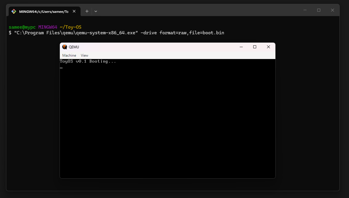
After building the bootloader, I tested it using QEMU to simulate how a real machine would boot the binary. I ran the command "C:\Program Files\qemu\qemu-system-x86_64.exe" -drive format=raw,file=boot.bin, which loads the boot.bin file as a raw disk image and starts the virtual machine. This allows me to see exactly how the BIOS would execute my bootloader in a real system. When QEMU starts, it successfully loads the boot sector and displays the output on the screen, confirming that the boot process and BIOS interrupts are working correctly.
Phase 2 - Protected Mode + GDT
Before writing any code for this phase, it helps to be clear about what problem we are actually solving, because it is easy to get lost in descriptor byte layouts and lose sight of why any of it is needed in the first place.
Real mode, the environment our Phase 1 bootloader ran in, has two limits that an operating system simply cannot live with. Every address is built from a 16-bit segment and a 16-bit offset, which caps addressable memory at 1 MB no matter how much RAM is actually installed. And there is no protection of any kind. Any code running in real mode can read or write any byte of memory it wants, with nothing stopping it. Protected mode, introduced with the 80286 and extended significantly by the 80386, removes both of these limits by giving us 32-bit registers and addressing, reaching a full 4 GB, along with a mechanism the CPU itself uses to enforce which code is allowed to touch which memory.
So the entire goal of Phase 2, stated plainly, is to flip the CPU from 16-bit real mode into 32-bit protected mode and prove that it worked. Everything else covered below is really just the setup required before that switch is allowed to happen.
The full source code for this phase is available in the repository. The exact commit can be found here: Phase 2 Protected Mode Commit
The GDT, a table the CPU insists on seeing first
The CPU does not let us simply turn on protected mode and move along. Before allowing the switch, it expects to be handed a table in memory that describes the memory layout: what segments exist, where they start, how big they are, and what is allowed to happen inside each one. This table is called the Global Descriptor Table, or GDT.
This plays a similar role to something we already did in Phase 1. When we set DS, ES, and SS to 0 at the very start, we were telling the CPU how to interpret segment registers under real mode's addressing rules. The GDT does the same kind of job for protected mode, just in a much more expressive way. Instead of one flat assumption, each entry in the table can describe a completely different region of memory along with its own base address, size, and permission rules.
Every protected mode system needs at least three entries in this table.
- A null descriptor, required to be all zeros and never actually used to address memory
- A code segment descriptor, describing a region of memory allowed to hold executable instructions
- A data segment descriptor, describing a region of memory allowed to hold readable and writable data
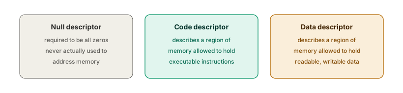
For this phase we use what is called a flat memory model, where both the code and data descriptors describe the entire 4 GB address space starting at base address 0. In other words, the two descriptors completely overlap. On its own this looks pointless. If both descriptors cover the exact same range, what is the point of having two separate entries at all?
The answer is that protected mode requires the CPU to consult the GDT for every memory access, regardless of whether the segments actually restrict anything. We still need valid, correctly formed descriptors to satisfy that requirement, even though we are choosing not to use them for real protection just yet. Genuine memory protection between kernel and user space comes later, once paging is introduced in a future phase. For now we keep the GDT as simple as possible on purpose, so that the one goal of this phase, switching modes successfully, is not tangled up with a second hard problem at the same time.
Anatomy of a segment descriptor
Each entry in the GDT is exactly 8 bytes, no more and no less. This is a hardware defined format, not something we get to choose, the same way the boot sector had to be exactly 512 bytes with the boot signature sitting in exactly the last two.
Conceptually, a descriptor only needs to express three things: where the segment starts (the base), how big it is (the limit), and what kind of segment it is along with who is allowed to use it (the access rules). The awkward part is how these get packed into exactly 8 bytes. The base address is a single 32-bit number and the limit can be up to 20 bits, and neither of those fits into any single byte or word sized box available in assembly. So each one is split into several pieces and scattered across the descriptor.
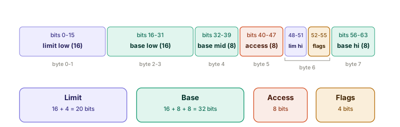
It is worth being clear that there is only one base value and only one limit value here. Each is simply broken into pieces because no single storage box is wide enough to hold the whole number, the same way a number too large for one card would need to be written across several cards. The CPU reassembles the pieces back into a single number when it reads the descriptor.
The reason the pieces sit in this particular scattered order rather than together cleanly is historical. The format comes from the 80286, which only supported a 24-bit base address, so the original layout only needed two pieces for the base. When the 80386 later extended protected mode to a full 32-bit base, backward compatibility meant the existing layout could not simply be redesigned. The only option was to tack the extra base byte onto the very end of the descriptor, byte 7, as a later addition rather than a clean rebuild.
In NASM this is expressed with two different box sizes, dw for a 2-byte word and db for a single byte. Adding up 2 + 2 + 1 + 1 + 1 + 1 comes to exactly 8 bytes, matching what the CPU expects.
The access byte
Of the eight bytes, the access byte is where a descriptor's actual meaning lives. It is what separates a code segment from a data segment, and it defines who is allowed to use it.
Bit 7 – Present
: Must be 1 for a valid, usable segment.
Bits 6–5 – Privilege Level (DPL)
: 00 = Ring 0 (kernel level).
Bit 4 – Descriptor Type (S)
: 1 for a normal code or data segment.
Bit 3 – Executable (E)
: 1 = Code segment, 0 = Data segment.
Bit 2 – Direction / Conforming (DC)
: Leave as 0 for our purposes.
Bit 1 – Readable / Writable (RW)
: For code segments, 1 means readable. For data segments, 1 means writable.
Bit 0 – Accessed (A) : Set automatically by the CPU when the segment is accessed.
For the code descriptor we want present, kernel level, executable, and readable. Written as bits that is 10011010, which is 0x9A. For the data descriptor, only bit 3 changes since it is not executable, and bit 1 now means writable instead of readable, giving us 10010010, which is 0x92.
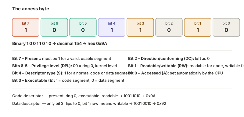
This is the same kind of packed bits idea as bl = 0x04 from Phase 1's print_string, where a single byte's bits controlled the text attribute passed to the BIOS. Here, a single byte's bits control a segment's type and permissions instead.
The flags nibble and the granularity trick
Sitting alongside the last 4 bits of the limit, in byte 6, is a 4-bit flags field that changes how the limit value gets interpreted.
The granularity bit, when set, tells the CPU to multiply the limit by 4 KB instead of treating it as a raw byte count. This is what lets a fairly small limit field stretch out to describe the full 4 GB range. The size bit, when set, marks this as a 32-bit segment, matching the [BITS 32] code that runs once we are in protected mode. With both bits set, combined with the remaining limit bits, this byte becomes 0xCF.
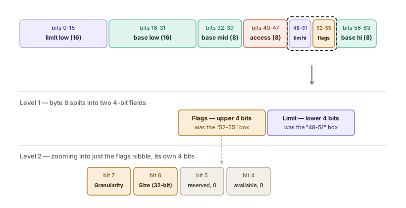
The null descriptor
The very first entry in the GDT is deliberately different from the other two. It is simply 8 zero bytes.
gdt_null:
    dq 0x0000000000000000
dq (define quad-word) is a single 8-byte box, so this one line is the entire null descriptor by itself, with no need to assemble it from smaller pieces the way the code and data descriptors are.
The reason this entry exists, and exists specifically as invalid, comes down to how segment registers work in protected mode. A segment register no longer holds a raw address directly, it holds a selector, which works as an index into the GDT telling the CPU which descriptor entry to use. Selector 0 naturally points at entry 0.
If entry 0 described a real, valid, usable segment, then any bug that left a segment register accidentally set to 0, say a register that was never properly initialized, would be silently accepted by the CPU as a legitimate segment. The mistake would go completely unnoticed. By making entry 0 explicitly null and invalid, the CPU is designed so that any attempt to actually use selector 0 for a memory access triggers an immediate fault. That fault is a loud, catchable signal that some segment register was left unset, rather than a silent bug that surfaces later as a confusing crash. It plays the same role as the 0x55 0xAA boot signature check from Phase 1, a deliberate sanity marker that turns a class of mistakes into something the hardware catches right away.
The code and data descriptors
With the access byte and flags understood, the full code and data descriptors follow directly from everything above, both using base 0 and the maximum limit, differing only in the access byte.
gdt_code:
    dw 0xFFFF        ; limit (low 16 bits)
    dw 0x0000        ; base  (low 16 bits)
    db 0x00          ; base  (next 8 bits)
    db 0x9A          ; access byte: present, ring0, code, readable
    db 0xCF          ; flags (4K granularity, 32-bit) + limit (high 4 bits)
    db 0x00          ; base  (final 8 bits)

gdt_data:
    dw 0xFFFF
    dw 0x0000
    db 0x00
    db 0x92          ; access byte: present, ring0, data, writable
    db 0xCF
    db 0x00
Reading gdt_code one line at a time, the first dw 0xFFFF is the low 16 bits of limit, every bit set, the maximum a 16-bit box can hold. The next dw 0x0000 is the low 16 bits of base, and the following db 0x00 is the next 8 bits of that same base, both zero, since this segment starts at address 0. db 0x9A is the whole access byte, present, ring 0, executable, readable, worked out earlier bit by bit. db 0xCF does two jobs in one byte, its upper nibble sets the granularity and size flags, its lower nibble supplies limit's final 4 bits, also all ones, matching the maximum we're aiming for. The last db 0x00 is the final 8 bits of base, completing it as 0x00000000.
Pulling every piece back together into the four fields it actually describes:
Base   = 0x00 (low) + 0x00 (mid) + 0x00 (high) = 0x00000000, starts at address 0
Limit  = 0xFFFF (low) + 0xF (high, from 0xCF's lower nibble) = 0xFFFFF, the maximum 20-bit value
Access = 0x9A, present, ring 0, code, readable
Flags  = 0xC (from 0xCF's upper nibble), granularity on, 32-bit size on
So reading this descriptor as one sentence, it describes a segment starting at address 0, stretching across the maximum limit the format allows, which the granularity bit then expands from roughly 1 MB into the full 4 GB range, holding executable, readable, 32-bit code.
gdt_data is built the exact same way, base 0, limit 0xFFFFF, granularity and size flags on, the only line that changes is the access byte itself. 0x92 differs from 0x9A in exactly one bit, bit 3, executable, which flips from 1 to 0 since this is data rather than code, and that same flip changes what bit 1 means, from readable to writable. Every other byte in the two descriptors is identical, since a flat code segment and a flat data segment are meant to describe the same region of memory, just with different rules for what's allowed to happen inside it.
Telling the CPU where the table is
Building the table in memory is not enough on its own. The CPU still needs to be told where it lives and how big it is. This is done with the lgdt instruction, which loads a small 6-byte structure into an internal CPU register.
Bytes 0-1 : Size of the GDT, minus 1
Bytes 2-5 : Linear address where the GDT starts
gdt_end:

gdt_descriptor:
    dw gdt_end - gdt_null - 1
    dd gdt_null

CODE_SEG equ gdt_code - gdt_null
DATA_SEG equ gdt_data - gdt_null
gdt_end is just a label, a marker placed immediately after gdt_data, giving us a fixed point NASM can measure from. It does not reserve any bytes itself, it simply marks the exact position where our table stops.
gdt_descriptor is the 6-byte structure lgdt actually reads, and it is built from the two fields above. gdt_end - gdt_null gives the total size of our table, three entries at 8 bytes each, 24 bytes. We then subtract 1, landing on 23, since the CPU treats this field as the address of the last valid byte in the table rather than a plain count, the same kind of fixed hardware quirk we already saw with the boot signature needing to sit at exactly the final two bytes of the sector, no more and no less. The second field, dd gdt_null, stores the actual address where the table begins, since gdt_null marks the first byte of the first entry.
Once lgdt [gdt_descriptor] runs, the CPU reads these exact 6 bytes and loads both values into its own internal register, so from that point on it knows both where the table starts and where it is allowed to stop looking.
The last two lines are a different kind of thing entirely, not part of this 6-byte structure at all, and not stored in memory. CODE_SEG and DATA_SEG are constants NASM calculates while assembling the file. Each one is the byte offset of a descriptor from the start of the table, gdt_code - gdt_null comes out to 8, gdt_data - gdt_null comes out to 16. These offsets are exactly what a segment selector is, so these two constants are the real values we load into segment registers once protected mode is active, whether directly, as in mov ax, DATA_SEG, or as part of the far jump, jmp CODE_SEG:init_pm. They exist purely so the rest of the code can refer to CODE_SEG and DATA_SEG by name instead of hardcoding 8 and 16 everywhere. Selector 0, pointing at the null descriptor, is deliberately never produced by either of these constants, since neither gdt_code nor gdt_data sits at the very start of the table.
The actual switch
With the table built and ready, flipping the CPU into protected mode is a short, rigid sequence of four steps. Getting any one of them out of order tends to crash the CPU immediately with no error message at all, most commonly seen as QEMU simply rebooting instantly.
switch_to_pm:
    cli                          ; 1. disable interrupts
    lgdt [gdt_descriptor]        ; 2. load the GDT

    mov eax, cr0                 ; 3. set the PE bit in CR0
    or eax, 0x1
    mov cr0, eax

    jmp CODE_SEG:init_pm         ; 4. far jump to flush the pipeline
Step 1, cli. Interrupts are disabled first. In Phase 1, interrupts were never a concern because BIOS handled them and nothing about real mode's rules was being changed. Here, we are about to change those rules entirely, and if a hardware interrupt fired mid transition, the CPU would try to service it using real mode interrupt handling that is about to become meaningless, leading straight to a crash.
Step 2, lgdt [gdt_descriptor]. This reads our 6-byte gdt_descriptor structure, the size and address pair built earlier, and loads both values into the CPU's internal GDTR register. From this point on, the CPU knows where our GDT lives and how big it is. This step alone does not turn protected mode on, a GDT can be fully loaded while the CPU is still sitting in real mode, completely unused.
Step 3, the three CR0 lines. CR0 is a special control register holding various CPU mode flags, and bit 0 specifically is the Protection Enable bit, PE. Since individual bits inside CR0 can't be changed directly, we first copy it out into a normal register we're free to work with:
mov eax, cr0
Then comes the line that actually does the work:
or eax, 0x1
This is where the actual "turn protected mode on" logic happens, and it's worth understanding precisely why or is used here rather than something like just setting EAX directly to 1.
0x1 in binary is 00000000 00000000 00000000 00000001, just bit 0 set, every other bit 0. The or instruction compares each bit position between EAX and 0x1, and sets the result's bit to 1 if either input has a 1 there, otherwise 0.
Since every bit of 0x1 other than bit 0 is 0, or-ing with it can only possibly change bit 0. Whatever EAX's other bits were before, they're untouched, because x OR 0 = x for any bit x. But bit 0 specifically becomes guaranteed 1, because x OR 1 = 1, regardless of what it was before.
Before: EAX = ???????? ???????? ???????? ???????0   (bit 0 currently off, rest unknown/unchanged)
OR:              0x1 = 00000000 00000000 00000000 00000001
After:  EAX = ???????? ???????? ???????? ???????1   (bit 0 now on, everything else identical)
This matters because CR0 holds several other important flags besides PE, and we have no intention of touching any of them, we only want to flip this one specific bit on, safely, without accidentally disturbing anything else already configured in that register.
The modified value is then written back:
mov cr0, eax
The instant this completes, bit 0 of CR0 is 1, and the CPU is technically in protected mode. But this alone still isn't enough, because the CPU's instruction pipeline may already have upcoming instructions pre-fetched and partially decoded under the old real mode rules, and flipping this single bit does not retroactively fix them.
Step 4, the far jump. jmp CODE_SEG:init_pm is not an ordinary jump, it is a far jump, meaning it explicitly reloads the CS register with a new selector, CODE_SEG, at the same time as jumping to init_pm. This does two things at once. It flushes the CPU's prefetch queue, discarding anything decoded under the old real mode assumptions, and it forces CS to be reloaded using our new GDT based selector instead of its old real mode value. Skipping this step would leave CR0 reporting protected mode as active while CS still held a stale real mode value, a mismatch that leads to an immediate crash on the very next instruction fetch.
Landing in 32-bit code
[BITS 32]
init_pm:
    mov ax, DATA_SEG
    mov ds, ax
    mov ss, ax
    mov es, ax
    mov fs, ax
    mov gs, ax

    mov ebp, 0x90000
    mov esp, ebp
[BITS 32] tells NASM to switch how it encodes every following instruction, assuming 32-bit operands and addressing by default, mirroring [BITS 16] from the very top of the file, just marking the point where the CPU's own behavior actually changes.
The far jump already reloaded CS, but the remaining segment registers, DS, SS, ES, FS, and GS, still hold leftover real mode values and need to be pointed at our new data descriptor instead. This is the same instinct as Phase 1's initial segment setup, establishing a clean and known baseline before doing anything else.
We then set up a fresh 32-bit stack by pointing ESP at a safe, arbitrary address comfortably above where the bootloader and any future kernel code are loaded, the same idea as Phase 1's mov sp, 0x7C00, just repeated for the new mode with a different address and a wider register.
Why print_string stops working
Here is a consequence worth stating plainly, since it catches almost everyone doing this for the first time. int 0x10 stops working entirely the instant protected mode is active.
BIOS interrupt handlers are real mode only code. They rely on the real mode interrupt vector table and real mode addressing assumptions, none of which stay valid once the CPU has switched modes. Calling int 0x10 in protected mode does not fail politely, it crashes.
So proving that Phase 2 actually worked needs a different way of getting text onto the screen, one that does not depend on BIOS at all. There is a fixed memory address, 0xB8000, that is directly wired to the screen hardware in text mode. Any bytes written there show up immediately, with no BIOS involved. Each character on screen takes up 2 bytes at this address, one byte for the character itself and the next byte for its color attribute.
print_pm_string:
    pusha
    mov edx, 0xB8000
    mov esi, msg_pm
.loop:
    mov al, [esi]
    mov ah, 0x0F
    cmp al, 0
    je .done
    mov [edx], ax
    add esi, 1
    add edx, 2
    jmp .loop
.done:
    popa
    ret
The loop here follows the same shape as Phase 1's print_string, loading a byte, checking for the null terminator, printing it, and advancing. What changes is how the character actually reaches the screen. Instead of asking BIOS to draw it through int 0x10, we write the character and its color byte directly into the memory the video hardware is constantly reading from. Seeing this print successfully is the real proof that the CPU is genuinely running 32-bit protected mode code with no BIOS involvement left.
After building this phase, we tested it the same way as before, using QEMU to boot the raw binary directly. Running qemu-system-x86_64 -drive format=raw,file=boot.bin loads boot.bin and starts execution exactly where BIOS would on real hardware. The boot message from Phase 1 appears first as usual, followed immediately by a new line proving the switch into 32-bit protected mode worked, with no crash or reboot loop.
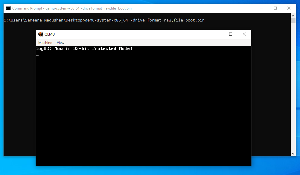
Phase 3 - Interrupts + Keyboard
Comming soon...